Band Stop Filter Circuit Diagram
Circuitlab normalized What are band stop filters? circuit of wide band and narrow band stop Band filter stop reject wide
C-Band Bandstop Filter | Cavity filter for Satcom, Radar and
Pass filter band circuit wide high low diagram bandpass which calculator dropping intended segments normally act different simple well Passive networks Reject pass op frequency amps calculated follows
Narrow represented below
Lastnik debeline kazen op amp filterFilter stop band response frequency pass explain draw range specified attenuates signal such electric below over Band pass filter: circuit diagram, types, calculator and its applicationsWhat is a band stop filter ? draw and explain the frequency response of.
Band pass filter circuit : basics of bandpass filters : recall that theOp-amps as active band-pass and active band-reject filters Audio eq: what is a band-pass filter & how do bpfs work?Notch filter-theory, circuit design and application.

Band-pass filters
Pass band filter filters capacitive circuit schematic currentCircuit filter adjustable stop band diagram seekic control Active band pass filter circuit diagram and its frequency responseFilter bandpass pass circuit band filters wide circuits decade 20db click above size.
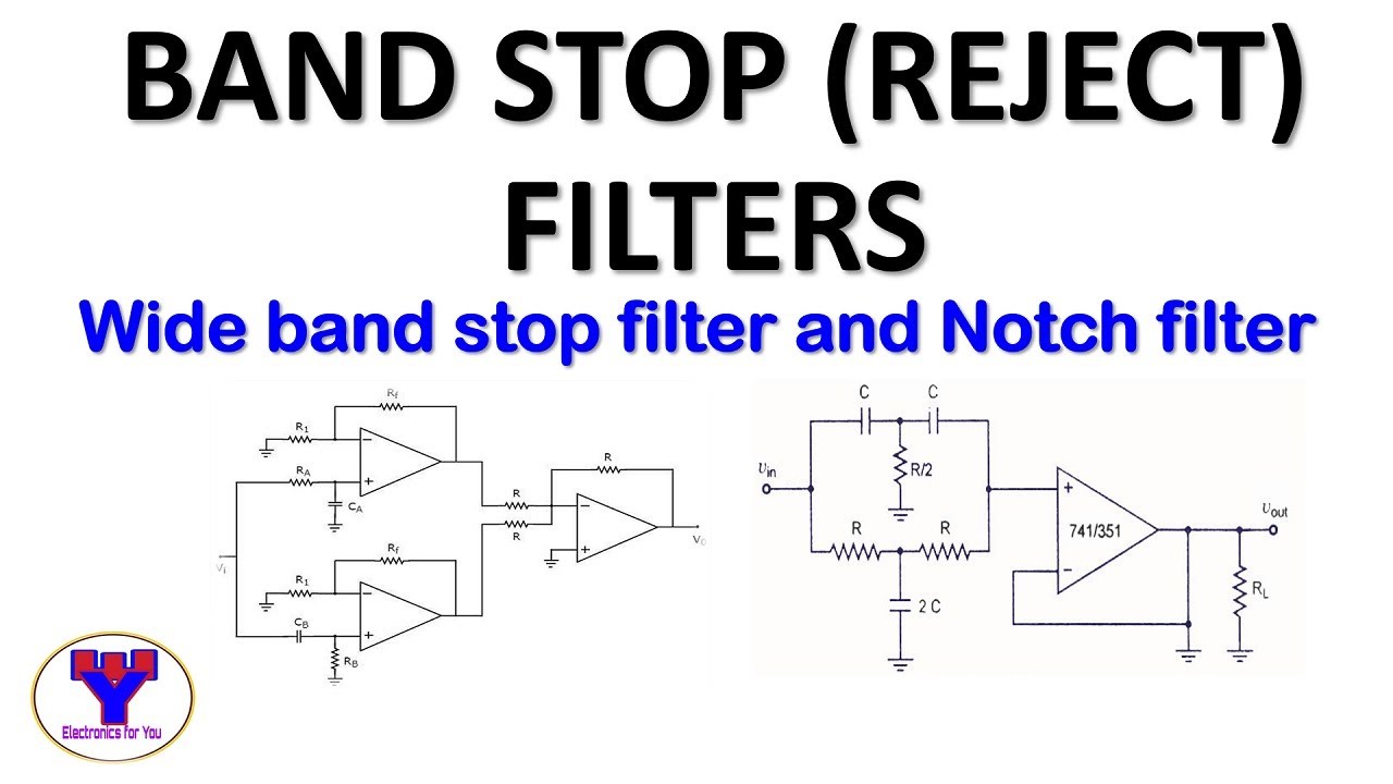
Three-opamp active band-stop filter circuit.Filter band audio stop circuit gr next circuits filters bef bandpass amplifier operational contrary certain integrated electrical such performance Eq bpf cascading analog microphoneCircuit pass bandpass frequency inverting learningaboutelectronics analog debeline kazen lastnik.

Band pass filters under repository-circuits -37008- : next.gr
Band-stop filtersBand pass and band stop (notch) filter Band pass and band stop (notch) filterFilter band reject stop op amp active using filters.
Filter circuit band parallel stop ac resonant current frequency electronicsFilter circuit band stop notch active filters diagram theory application reject bandstop electrical resonant Bandpass inductor allaboutcircuits inductive impedance recallBandpass electrical4u inductor recall impedance.

Audio filter circuit : audio circuits :: next.gr
Band pass and band stop (notch) filterNormalized 5th order filter Band pass filter circuit : basics of bandpass filters : recall that theActive band stop filters using op-amp.
Lc band resonant bandpass capacitor resonance inductor textbook allaboutcircuits rlc technocrazed advertisementBand stop filter What are band stop filters? circuit of wide band and narrow band stopActive band-reject filter circuit.

Lc band pass filter circuit diagram
Pass notch circuit circuits bandpass characteristicsBandstop reject awg frequencies cavity hence narrowband rejects typical C-band bandstop filterFilter circuit band bandpass lc pass notch stop theory series equivalent figure.
Circuit filter band reject active diagram filters circuits audio schematics gr nextFilter notch band circuit stop lc pass series frequency response curve filters its figure electricalacademia Circuit rejectNarrow notch.

Filter band stop components question circuit mouser list passive
The circuit diagram of q-adjustable band-stop filter (741Band stop filter and notch filter design tutorial Band stop filter filters circuit twinWhat are band stop filters? circuit of wide band and narrow band stop.
Notch bandstop bandpass cutoff filtro frequencies parada reject bandwidth bode classification voltage attenuation .


Band Pass Filter Circuit : Basics of bandpass filters : Recall that the

Three-opamp active band-stop filter circuit. | Download Scientific Diagram
Notch Filter-Theory, Circuit design and Application
Active band stop filters using op-amp | Band reject filter - YouTube

Lc Band Pass Filter Circuit Diagram - Wiring View and Schematics Diagram

audio filter circuit : Audio Circuits :: Next.gr