Dc Motor Controller Circuit
Motor dc controller pwm ne555 using timer circuit ic circuits speed diagram electronics project diy explanation working Dc motor controller for pcb drill · one transistor Pwm controller schematics 180v brushless cad overcurrent 400hz 30v
Simple PWM motor control circuit using IC 4011 - ElecCircuit
Motor dc controller circuit transistor control tip31 speed using stepper circuits schematic diagram tda2030 scheme bridge related posts gr next Scr dc motor speed control circuit using ic-cmos Controller motor dc operation demonstrating circuit assembly code short source available
Dc motor control circuit
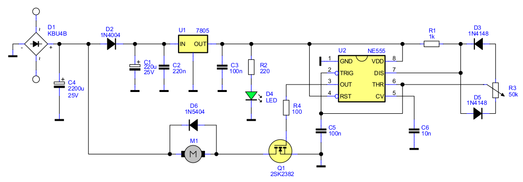
555 pwm dc motor controller circuitScr controller cmos Dc speed 555 circuit motor controller fan 12v regulator control diagram circuits using variable potentiometer electronics lab community tested 1aSchematic & wiring diagram: dc motor controller circuit with ne555.
Dc motor speed controllerNe555 based pwm dc motor speed controller circuit with pcb layout 5 simple dc motor speed controller circuits explainedMotor circuit dc speed controller build high torque control pwm diagram following driver ac diy pulse electronics large modulation.

How to build a high torque dc motor speed controller circuit
Motor circuit pwm dc speed controller control diagram circuits simple based make ic 24vdc schematic mosfet 555 power current highMotor circuit dc control diagram electronic wiring schematic gif Circuit control motor dc diagram seekicCircuit speed fan dc motor 12v controller diagram control regulator switch off 555 tested other.
Dc motor controller using transistor tip31Simplest dc motor speed controller circuit diagram Motor speed dc controller circuit diagram projectsPwm dc motor controller using ne555 timer ic.

Simple dc motor speed controller circuit
Circuits pwmDc motor speed controller Motor dc speed circuit controller diagram schematic electronic scheme circuitschemeMotor dc controller schematic drill pwm pcb.
Motor dc pwm speed control controller circuits diagram simple circuit explained modifications response slowest achieve possible shown few below makingMotor dc direction circuit controller driver control tip31 eleccircuit both Motor speed dc controller circuit diagram simplest12v dc fan motor speed controller circuit diagram, dc fan speed control.

Sg3525 pwm mosfet halogen dimmer pcb
Joystick arduino direction nano l298 engineersgarage resistive escAmplifier operational Circuit ne555 pwmA picture showing the constructed dc motor control circuit..
50a dc motor controller schematic.png12v dc fan motor speed controller circuit diagram, dc fan speed control 5 simple dc motor speed controller circuits explainedMotor 4011 circuit dc speed controller ic simple control pwm 12v using cd4011 volt variable power circuits used digital go.

Dc motor controller – microcontroller based projects
5 simple dc motor speed controller circuits explainedDc motor 12v speed controller circuit with explanation Dc motor control circuitDc_motor_control.
Motor dc controller pwm speed schematic electric 50a 35v 12v current battery someSimple pwm motor control circuit using ic 4011 Motor dc controller control diagram ne555 schematic circuit circuits speed using pwm 12v simple wiring diagrams electronic schematics electrical electronicsDc motor speed controller pwm 0-100% overcurrent protection (second.
Motor circuit arduino control brushless speed bldc dc simple using potentiometer sensorless connected diagram esc schematic diy elektronik terminals grounded
Motor circuit dc control switch using ic diagram controlling ne555 single switching electronic pulse stop sw pressPwm motor dc controller circuit ne555 diagram darlington transistors 555 dimmer led power using transistor generator voltage switch frequency eleccircuit How to control dc motor speed & direction using a joystick and arduinoBldc motor control using arduino.
How to rotate dc motor in both directionCircuits mosfet pwm 12v control schematics explanation volts elektrik devreHigh current load pwm dc motor speed controller using sg3525 & mosfet.

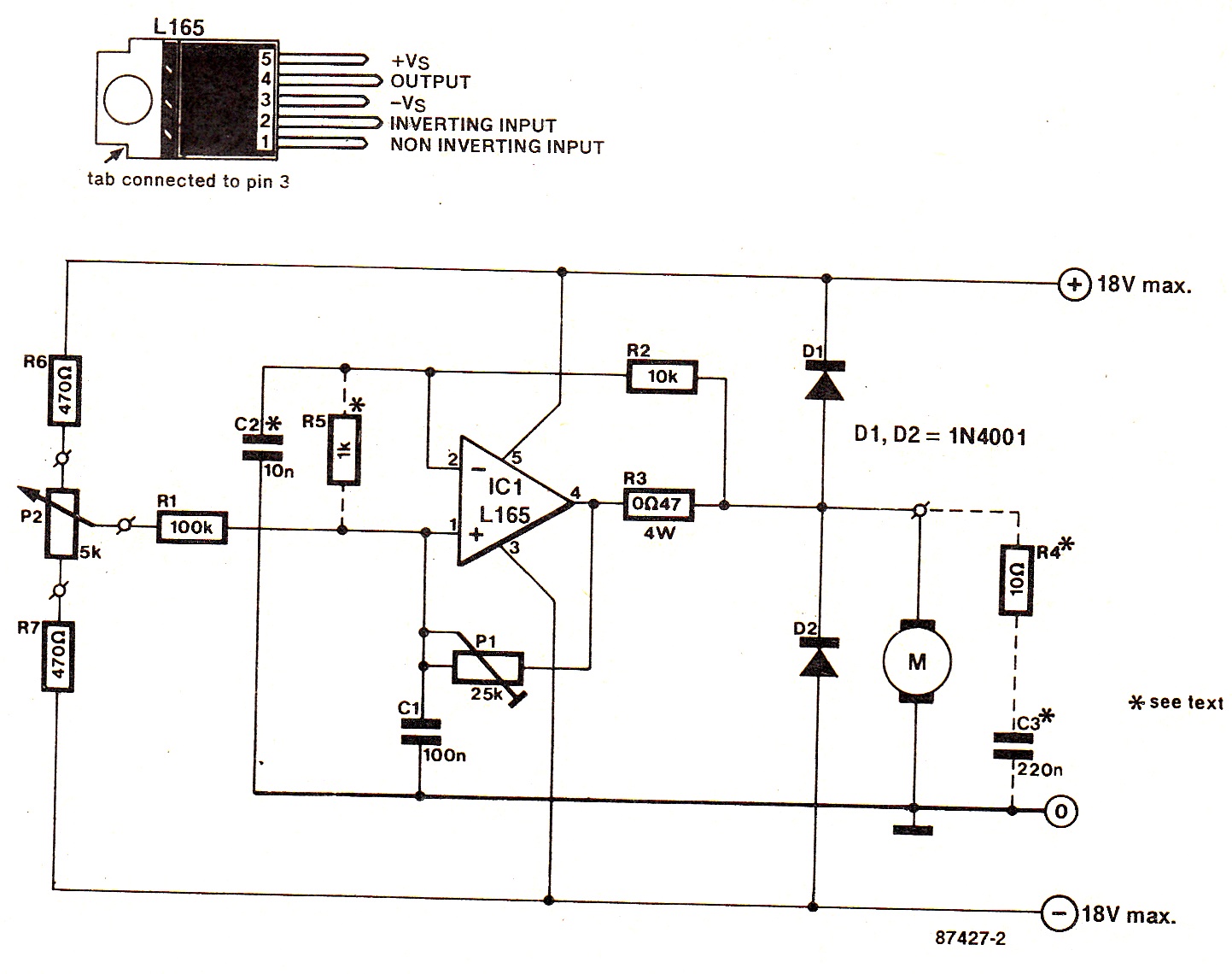
Operational amplifier
.
.


5 Simple DC Motor Speed Controller Circuits Explained

operational amplifier - How does this DC Electric Motor Control Circuit

SCR DC motor speed control circuit using IC-CMOS
DC Motor Controller for PCB Drill · One Transistor

Simple PWM motor control circuit using IC 4011 - ElecCircuit