Digital Timer Circuit Using 555
Counter circuit binary 555 timer diagram circuits electronic based ic using schematic projects diagrams gates circuitdigest gate choose board leds 555 timer circuit using light dancing diagram circuits pcb easyeda ne555 astable lm555 mode software cloud time delay Delay simple
LED Chaser using 4017 Counter and 555 Timer
Led chaser using 4017 counter and 555 timer Circuits blinking Digital clock circuit using ic 555 and ic 4026 – diy electronics projects
Adjustable timer circuits using ic 555
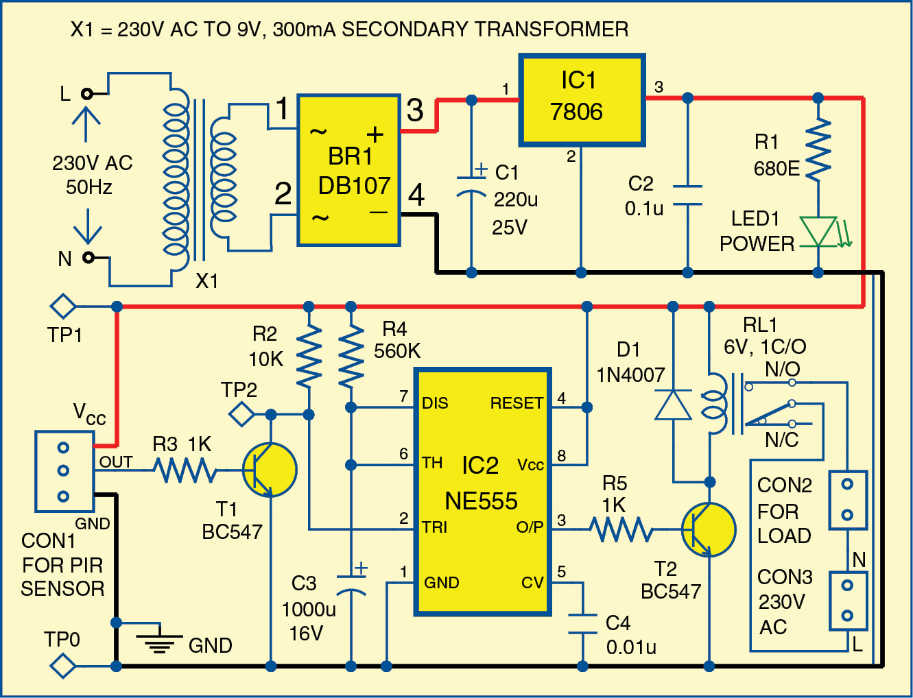
Motion circuit ne555 detector using timer simple diagram electronics electronic projects circuits fig14+ time delay circuit using 555 Clock digital circuit ic using 555 diy project diagram segment display electronics arduino board projects clocks basic hub above resolution555 monostable timer multivibrator circuit using diagram circuits schematic stable draw electronic oscillator unstable transmitter.
How does ne555 timer circuit work555 timer schematic : 555 timer circuits in proteus : in this category Circuit delay timer counterSimple motion detector using ne555 timer circuit.

555 astable circuit diagram timer multivibrator circuits calculator using electronic led mode off formulas
Circuit timer circuits using simple make 555 ic diagram switch buzzer adjustable delay ic555 minutes button connect electronic between please555 timer basics 555 timer tutorial: how it works and useful example circuitsDancing light using 555 timer.
555 timer astable multivibrator circuit diagramElectronic circuits and projects: 555 timer based binary counter circuit 555 timer circuitsIc 555 delay timer circuit.

Timer 555 schematic circuits slidetodoc
555 circuit ic led switching delay circuits timer off homemade time using projects relay diagram alternate 220v two board switchTimer 555 schematic How to make on/off delay timer circuit using 555 timer icTimer 555 circuit schematic electronic circuits control ic relay using simple charger next board battery multivibrator basic schematics driver timing.
555 clock timer circuit schematic build circuitos con using 60hz resistor learningaboutelectronics esquemas will breadboard produce shown below electricalElectrical and electronics circuit: how does a 555 timer work? How to build a clock circuit with a 555 timer555 timer diagram block circuit chip does ne555 datasheet inside pinout work works eleccircuit look function.

4017 555 led chaser timer using counter circuit diagram ic capacitor
555 timer led astable mode flashing photoresistor circuit blinking using potentiometer resistor capacitor light basics flash diagram circuitbasics make ohmMonstable multivibrator using 555 timer .
.


IC 555 Delay Timer circuit | Easy timer circuit | on off delay circuit

555 Timer Astable Multivibrator Circuit Diagram

555 Timer Basics - Astable Mode

Electrical and Electronics Circuit: How Does a 555 Timer Work?

Simple Motion Detector Using NE555 Timer Circuit | Electronic Circuits

Digital Clock Circuit Using IC 555 and IC 4026 – DIY Electronics Projects

555 Timer Tutorial: How It Works and Useful Example Circuits
555 Timer - Multisim Live