Positive And Negative Clamper Circuit Diagram
Clampers negative positive Clamper circuit positive biased example Explain clamper circuit with proper waveforms
☑ Diode Clamping Explained
Negative clamper circuit circuits positive level signal pushes hand if other electronics downwards biased peak meets zero said then Clamper positive circuits Clamper circuit positive operation clamping diode analysis network
Biased positive clamper circuit : example -1
Clamper circuitClamper circuits Circuit waveform clipping positive clamper negative diagram clamping clipper buffer frequency fig modulated diy engineersgarage outputClamper circuit negative working principle.
Clamper circuits biasedWhat are clamper circuits? definition, operating principle Clamper positive circuit circuits negative diode biasing ac signal biased reverse half gets time definitionWhat are the clampers circuits and how they work?.

Clamper negative circuit circuits positive electronics definition figure understand operation detailed order input
Positive & negative clamper circuitsDiode clamping circuit-positive and negative clamper,circuit,waveform Circuit clamper positive clampers circuitsNegative clamper circuit || working principle of negative clamper.
What are clamper circuits? definition, operating principleWhat are clamper circuits? definition, operating principle Diode clamper circuitsClamper circuit negative bias example clamping diode solved.

What are clamper circuits? definition, operating principle
Clamper diode circuits negative positive circuitWhat are the clampers circuits and how they work? Clamper circuits voltage unbiased definitionBiased positive clamper circuit : example.
Clamper negative bias positive clamping circuits waveform clamp figure inputDiode clamper circuits Clamper positive negative bias diode circuits biased cycle half☑ diode clamping explained.

Clamper diode circuits biasing input biased
Explain clamper circuit with proper waveformsWaveform clamping: positive & negative clamping circuit design Clamper positive clamping circuit diode negative circuits waveformClamper circuit positive diagram diode figure explain capacitor resistor proper waveforms consist shows which.
Circuit clamper positive biased hardClamper circuit negative input shift adds diagram dc shows figure Op amp clamping circuitNegative clamper circuit and solved example with bias.

Clamping or clamper circuits
.
.


What are Clamper Circuits? Definition, operating principle

Diode Clamper Circuits - The Engineering Knowledge

What are the clampers circuits and how they work? - EE-Vibes
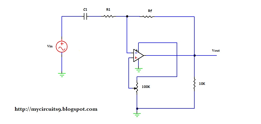
OP AMP CLAMPING CIRCUIT | My Circuits 9

What are Clamper Circuits? Definition, operating principle
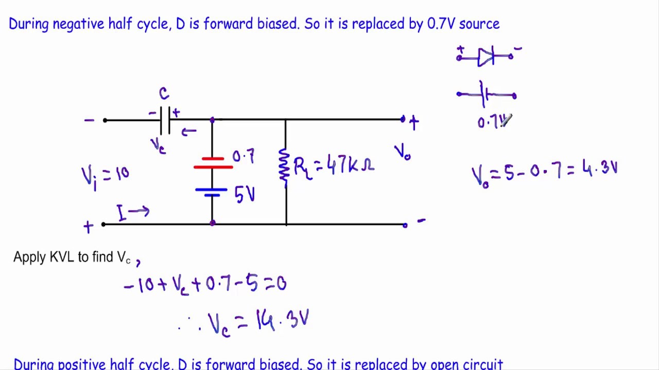
Biased Positive Clamper Circuit : Example - 2 (Very Hard) - YouTube

What are the clampers circuits and how they work? - EE-Vibes