Relay Board Circuit Diagram
Relay arduino module circuit 5v schematic diagram channel drive relays board electrical opto pins esp8266 isolated pump close lpt1 port Relay diagram board breakout circuit setting Relay wiring spst socket 40a fused schematic diode horn mgispeedware prong rocker wires lighted connect mgi accessory
pcb design - Why can't I trigger my relay? - Electrical Engineering
Relay board single 12v diagram diy circuit researchdesignlab Relay trigger why schematic pcb 5 pin relay wiring diagram
12v relay wiring diagram 5 pin
4 channel 5v relay moduleSimple relay switch circuit diagram 13+ 5v relay circuit diagram[diagram] 3 pin horn relay diagram wiring schematic full version hd.
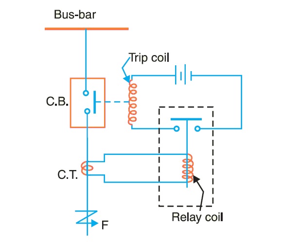
Relay board diagram arduino schematic control fan channel shield wiring channels above complete clickRelay 12v automotive Relays protective relay circuit diagram electrical working work typical system phase typesPcb relay.
8 channel lpt relay board
Relay breakout schematic circuit board pcbMbed: diy simple relay circuit board Relay module make schemCircuit relay simple board diy diagram led nc connected.
Relay moduleRelay schematic circuit output electronic Relay pcb electronic projectWiring understand principle.

Pcb design
What are protective relays?Final year project 2013/2014: week 3 of fyp 2 4 channel relay boardRelay relays uno l298 outputs inputs module mega shown bridge examples any using these.
2 channel relay boardRelay circuit Simple relay circuit and pcbSingle relay board.

Relay switch circuit use diagram simple ac basic wiring circuits using electronic electronics example board where lamp battery voltage ldr
How to make relay module circuit and pcb and earn moneyRelay pcb fzz fritzing Schematic diagram relay driver board projectBasic relay circuit.
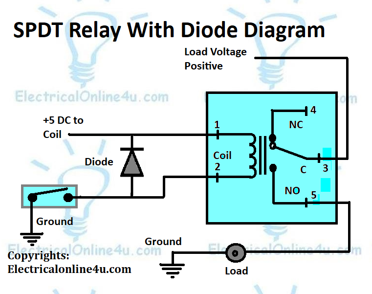
Relay schematic keep state circuit circuitlab created using electronicsDiagram relay circuit wiring el817 Relay wiring diagram and function explainedRelay use diagram wiring diode coil pole voltage single through.
How to build a control circuit with adjustable working time via wi-fi
Relay circuit earnRelay diagram wiring use pole double single his Relay layoutRelay module: a complete guide.
8-channel relay boardRelay schematic channel module circuit optocoupler 5v driver arduino control low power level electrical resolution supply wiki opto isolator port On the drawing board: relay boardRelay circuit and breakout board.

Schematic diagram relay driver board project
Board relay drawing5v sunfounder Schematic relay channel board lpt lab electronics power project pcb connectionMbed: diy simple relay circuit board.
220v relay relays schematic problem using arduino board mention forgot drive had stackRelay relays transistors transistor diagrams scheme vectormine ourpcb Relay channel schematic board circuit arduino pcb connection topic electronics lab control outputHow to make your own relay module.

Electronic project: relay board pcb
5 pin relay wiring diagramHow to make relay module circuit and pcb and earn money .
.


Relay Module: A Complete Guide

13+ 5V Relay Circuit Diagram | Robhosking Diagram

Simple Relay Circuit and PCB

Relays - MECControl

8-Channel Relay Board