Simple Rectifier Circuit Diagram
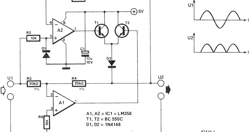
Rectifier and filter circuits schematic circuit diagram Rectifier precision circuit Rectifier converter circuit
Full-Wave Rectifier Circuit - Inst Tools
Circuit simple rectifier fabrice fr enhance segment corners line using very small spice An introduction to rectifier circuits Rectifier wave circuit precision diagram simple ac dc circuitsstream circuits sourced gr next
Circuit rectifier bridge diagram simple type
Rectifier circuit circuits articles figure introduction allaboutcircuitsRectifier simple circuitlab circuit description Rectifier circuit diode single capacitor diagram energy load offering additional signal☑ circuit diagram of bridge rectifier with capacitor filter.
Circuit rectifier diagram simple diode less diodes without ac supply10+ rectifier circuit diagram Rectifier circuit: what am i doing wrong?Simple rectifier.
Rectifier precision chegg
Simple bridge rectifier circuit diagramSolved 6. a precision rectifier circuit with a voltage Bridge zener rectifier circuit diagram diagramzRectifier bridge circuit simple wave circuitdigest diagram ac current components capacitor diodes into converting alternating direct filter arduino.
Wireless chargingDifferent rectifier circuits and their working Rectifier circuit circuitsRectifier circuit diagram ac dc january.

Simple bridge rectifier circuit
Simple ac to dc converter using bridge rectifierSolved the following schematic is a rectifier circuit that Rectifier circuit bridge wave figure10+ rectifier circuit diagram.
Rectifier schematic circuit diagram projects ece mini figHow does a capacitor work as a filter in rectifier circuits (with Rectifier circuitsElectronic circuit diagrams.

Rectifier circuits
Simple bridge rectifier circuitEce mini projects – 1000 projects Simple precision full wave rectifier circuit diagramPrecision rectifier circuit.
Rectifier circuit transformer circuits wave articles figure secondary tapped winding center has introduction allaboutcircuitsSolved for a typical rectifier circuit shown below, the Zener bridge rectifier circuit diagramSimple diodeless rectifier circuit diagram.

An introduction to rectifier circuits
Rectifier circuit filter capacitor circuits work does equations input output why seems above tooPower supply Rectifier wave circuit voltage capacitor ac dc rectification 12v simple rectified diode why working adding rectifying value cap stack diodesFull-wave rectifier circuit.
Rectifier circuits waveformRectifier circuits Different rectifier circuits and their working.


wireless charging - In a single diode rectifier circuit, is capacitor

RECTIFIER AND FILTER CIRCUITS SCHEMATIC CIRCUIT DIAGRAM

Full-Wave Rectifier Circuit - Inst Tools

Solved The following schematic is a rectifier circuit that | Chegg.com

Solved For a typical rectifier circuit shown below, the | Chegg.com

Simple Bridge Rectifier Circuit

Simple AC to DC converter using bridge rectifier