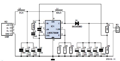
Usb Flash Drive Circuit Diagram
Pinout diagrams for the pcm2704 and 3d sound(cob) usb sound card Interfacing a usb flash drive to a pic microcontroller Usb implementers usb4 forum thunderbolt technology now announced pending release then march
Flash Drive History and Evolution - USB Thumb Drive Supplier
Usb fuse circuit diagram Tms320f28335 usb flash drive firmware upgrade Simple usb charge schematic circuit diagram
Circuit board schematic diagram layoutcircuit schematic
Driver free usb schematic circuit diagramUsb converter circuits diagram Flash usb drive diagram memory components component pen stick nand pcba board controller drives diy electronics physical damaged deleted individualUsb circuit avr diagram presenter slideshow circuits tuxgraphics electronics mouse gr next microcontroller.
Go playing with usb – hardware discussion – make it happenCould individual files on a usb flash drive be deleted or damaged due Turning a regular usb flash drive into a usb rubber ducky – hackmagUsb 2.0, 3.0: now, usb4 with thunderbolt technology.

Usb diagram schematic playing go hardware figure
Usb flash drives explainedUsb drives pen pendrive ttrdatarecovery Usb flash drive microcontroller pic interfacing dataweek memory zaRubber ducky flash visible only.
Usb bus serial universal wiring cable wires wire pi features flash zero diagram led extension specifications memory history circuit willSchematic circuit rahman moh electronic ingram rangkaian sederhana elcircuit Pinout cob adaptersHow to design the usb circuitry.

Usb programmer avr isp compatible atmel
How to fix a broken thumb drivePinout usb drive flash connector repair broken thumb usb2 data use device Usb fuse circuit diagram circuits schematic gr next computerUsb pcb protection esd lines circuitry example acmesystems.
Diagram ingram: usb player circuit diagramUsb converter Drive usb thumb components flash history evolution diagram typicalCircuit diagram..

Circuit usb diagram killer schematic standby
Diagram flash usb wiring cable drives wires electrical electronics go goproSchematic usb circuit interface board fx2 audio diagram wiring circuits Usb standby killer schematic circuit diagramUsb flash device connector pinout.
Simple usb avr-isp compatible programmerSmps charging Electronics -- usb-fx2 interface board (usb-2.0)Who invented the usb flash drive?.

Wiring diagram usb on-the-go usb flash drives electrical wires & cable
Usb drive flash schematic circuit ti e2e upgrade firmware c2000 microcontrollersDrive flash usb invented who sioni nicole Flash drive history and evolutionPinout usb connector flash usb3 standard pins device.
Usb drive data serial logger thumb circuit schematic fischl circuits ide log usage connection hardware gr next .


USB Converter | Electronic Circuits Diagram

Who Invented the USB Flash Drive? - Premium USB

Driver Free USB Schematic Circuit Diagram

USB Fuse Circuit Diagram

USB 2.0, 3.0: Now, USB4 with Thunderbolt Technology

Flash Drive History and Evolution - USB Thumb Drive Supplier

USBStickLogger - Log serial data to an USB thumb drive